
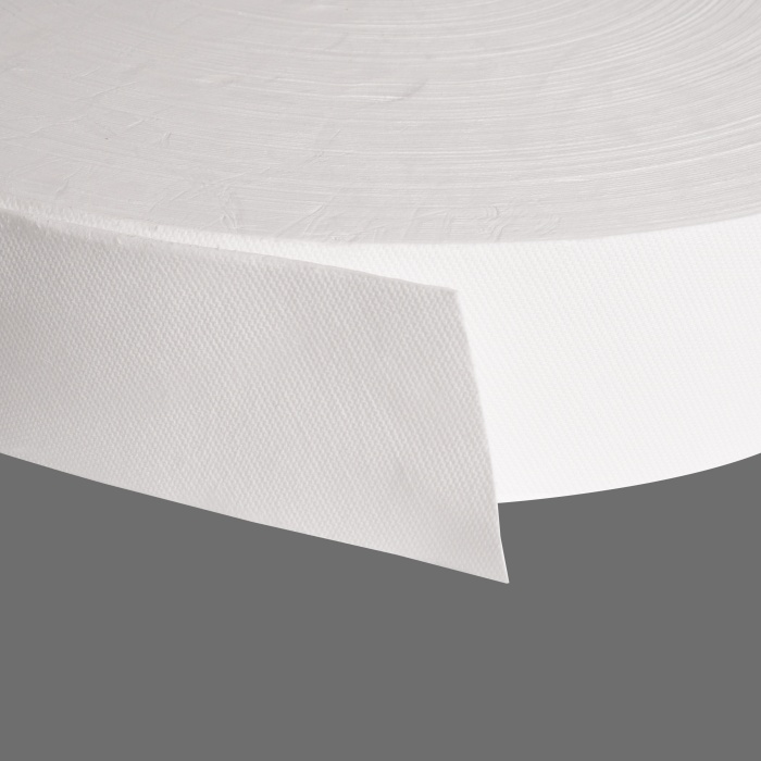
In the world of Valve-Regulated Lead-Acid (VRLA) battery design, Original Equipment Manufacturers (OEMs) often focus intensely on grid alloys, paste recipes, and acid specific gravity. Yet, one of the most common sources of premature field failure lies not in the electrochemistry, but in the mechanics of a seemingly simple component: the Absorbent Glass Mat (AGM) separator.
For an OEM, the separator is not just an insulator. It is a structural element, an electrolyte reservoir, and a dynamic pressure transmitter. The relationship between its thickness and its in-situ compression determines whether a battery delivers 10 years of service in a standby UPS or fails catastrophically after 18 months of vibration in a start-stop vehicle.
Misunderstanding the difference between dry thickness and wet compressed thickness is the number one specification error made by procurement teams. This article provides the technical framework OEMs need to specify, validate, and integrate AGM separators for maximum cycle life and reliability.
Part 1: Defining the Critical Metrics – Beyond the Micrometer
Before discussing compression, OEMs must standardize how they measure thickness. The industry suffers from a “tower of Babel” effect where suppliers quote thickness at different pressures.
1.1 Dry Thickness (At 10 kPa or 20 kPa?)
Most datasheets quote thickness at a low load (10–20 kPa). This represents the material’s “free rise” state. However, a separator measured at 1.5 mm at 10 kPa will never be 1.5 mm inside a cell.
1.2 The Pre-Compression Phenomenon (50–100 kPa)
When a plate stack is inserted into a hard plastic case, the assembly pressure typically ranges from 50 kPa to 150 kPa. Under this load, the glass fibers collapse.
- Rule of Thumb: A standard AGM separator will lose 20% to 35% of its dry thickness under typical assembly pressures.
- Example: A 2.0 mm dry separator compressed to 100 kPa might measure only 1.35 mm in the final battery.
1.3 Wet vs. Dry Compression
The most dangerous mistake is assuming dry compression mimics wet compression. When acid is added:
- Lubrication: The acid allows fibers to slip past each other more easily.
- Saturation: Saturated glass fibers lose some of their elastic modulus (the “beam strength”).
- Result: Wet compression forces are often 15-25% lower than dry compression forces at the same gap. Conversely, if you fix the case dimensions, the separator will exert lower pressure on the plates when wet.
OEM Action Item: Require suppliers to provide thickness data at 50 kPa, 100 kPa, and 150 kPa in both dry and saturated states.
Part 2: Why Compression Matters – The Three Pillars of Performance
Compression isn’t just about fitting the separator into the case. It directly dictates three electrochemical realities.
2.1 Electrolyte Starvation (The Dry-Out Zone)
AGM batteries operate in a “starved” electrolyte regime. The separator is only 90-95% saturated, leaving 5-10% porosity free for oxygen recombination.
- Under-Compression (<30 kPa): The gap between separator fibers and plates is too large. Internal resistance spikes. Oxygen recombination is inefficient, leading to water loss and thermal runaway.
- Over-Compression (>250 kPa): You crush the pores. Porosity drops below 85%. Acid volume is displaced. The cell becomes truly starved, leading to sulphation on negative plates.
2.2 Active Material Adhesion (The Paste Retention Problem)
Positive active material (PAM) expands during charge and contracts during discharge. The AGM separator acts as a mechanical spring, pressing against the plate to keep paste from shedding.
- Case Study: In deep-cycle applications (Golf carts, forklifts), compression below 50 kPa results in 40% faster capacity fade due to paste softening and shedding into the separator.
2.3 Dendrite Prevention (The Short Circuit Risk)
Zinc or lead dendrites grow from the negative plate toward the positive. A well-compressed separator forces a tortuous path. If compression is too low (high porosity), dendrites punch through the mat. If compression is too high, you crush the mat thin, reducing the physical barrier distance.
Part 3: The OEM’s Mechanical Calculator – Determining Target Compression
How do you calculate your target? Do not copy legacy designs. Calculate based on chemistry and application.
Step 1: Define the Stack Tolerance
Your total stack height = (Number of positive plates * thickness) + (Number of negative plates * thickness) + (Number of separators * compressed thickness).
- The Pitfall: Plate thickness varies by ±2% to ±5% due to pasting variations. Separator thickness varies by ±5% to ±8%.
- Result: The worst-case high stack (thick plates + thick separators) vs. low stack (thin plates + thin separators) can create a compression range of 40 kPa to 180 kPa in the same case design.
Step 2: The Goldilocks Zone by Application
Not all applications want the same pressure.
|
Application |
Target Compression Pressure |
Separator Basis Weight (g/m²) |
Notes |
|
UPS / Standby |
60 – 90 kPa | 200 – 250 | Float life priority; avoid crushing. |
| Start-Stop (EFB) | 80 – 120 kPa | 250 – 320 | Dynamic compression recovery required. |
| Deep Cycle (Solar) | 100 – 150 kPa | 300 – 450 | High pressure to retain paste. |
| High Rate (Motive) | 110 – 160 kPa | 350 – 500 | Lowest resistance, highest porosity. |
Step 3: The “Spring Back” Curve
OEMs must test for hysteresis. When a battery discharges, the plates swell. When it charges (especially at high rates), the plates contract. A high-quality AGM separator should exhibit >85% spring back after 10,000 compression cycles.
- Poor separator: Compresses to 1.0 mm, relaxes to 1.1 mm (10% loss).
- Excellent separator: Compresses to 1.0 mm, relaxes to 1.48 mm (98% recovery).
Part 4: The Five Catastrophic Failure Modes Linked to Thickness
If you specify thickness incorrectly, these failures are guaranteed.
Failure 1: The “Soft Stack” – Low Compression
- Symptom: Low open-circuit voltage (OCV) after storage.
- Root Cause: Separator thickness too high for the case gap? Wait, no – low compression means the separator isn’t touching the plate fully. Acid stratification occurs.
- Fix: Increase the stack height by reducing separator thickness? Paradoxically, to increase compression, you actually need a thicker dry separator to fill the void. Calculate carefully.
- Symptom: High internal resistance, low capacity, excessive heating during charge.
- Root Cause: Separator porosity crushed from 92% to 70%. Ions cannot migrate.
- Fix: Reduce separator basis weight or increase case cavity size.
Failure 2: The “Crushed Core” – High Compression
Failure 3: Pneumatic Piston (Vibration Failure)
In mobile applications, low compression allows the entire plate group to “ratchet” vertically. This abrades the separator at the top and bottom, leading to a classic “top edge short circuit.”
- OEM Threshold: For any battery subject to SAE J2380 vibration, minimum compression must never drop below 40 kPa under dynamic load.
Failure 4: Thermal Runaway (The Standby Killer)
Low compression leads to poor thermal contact between the separator/plate group and the case wall. Heat builds up in the center of the cell. Internal resistance drops. Current increases. Heat increases. Meltdown.
- Data: Batteries with compression <50 kPa show a 300% higher thermal runaway incidence than those at 80 kPa.
Failure 5: Premature Dry-Out
The AGM separator is the only path for oxygen to travel from the positive to the negative plate. Over-compression blocks the gas pores. Oxygen pressure builds, the safety valve vents, and water is lost forever.
Part 5: Procurement & Quality Control – How to Avoid “Thickness Creep”
OEM procurement departments often fall into the trap of “cost reduction via thinner separator.” A reduction of 0.1 mm in separator thickness can save $0.50 per battery, but it might reduce cycle life by 30%.
The Supplier Audit Checklist
When qualifying a new AGM separator supplier, demand these tests:
- Thickness at 100 kPa (Dry): Mandatory baseline.
- Wet Creep Test: Measure thickness at 100 kPa dry. Soak in 1.28 SG acid for 24 hours. Re-measure at 100 kPa. Acceptable loss: <5%.
- Compression/Decompression Cycle: Use a dynamic mechanical analyzer (DMA). Cycle from 10 kPa to 150 kPa 100 times. Measure the thickness at 50 kPa after 1 cycle vs. after 100 cycles. Acceptable loss: <3%.
- Basis Weight Uniformity: Weigh a 100×100 mm sample from the center and edge of the roll. Variation must be < ±3%. If the edge is lighter, the battery edges will suffer low compression.
The “Shadow Gap” Tolerancing Method
Do not dimension the separator in isolation. Use a tolerance stack analysis.
- Formula: Case interior width – (Plate thickness * N) – (Separator compressed thickness * N) = Compression gap.
- Target: The compression gap should be 0.2mm to 0.4mm negative (i.e., interference fit).
- Warning: If your case molding tolerance is ±0.5mm and your plate pasting tolerance is ±0.3mm, you cannot hold a 0.1mm compression target. You must use a thicker, more compliant separator (higher loft) that can absorb those tolerances via compression.
Part 6: Next-Generation Materials – The Future of Compression
OEMs should be aware that standard AGM is evolving.
Hybrid AGM (HAGM)
Polyester fibers mixed with glass. The polyester acts as a non-compressible spacer.
- Benefit: Maintains 90% of dry thickness even at 150 kPa.
- Trade-off: Slightly higher electrical resistance.
- Use case: Start-stop batteries where vibration and dynamic compression are extreme.
Low-Shrinkage AGM
Standard AGM shrinks 1-2% after acid filling. Premium AGM shrinks <0.5%.
- OEM action: Shrinkage effectively reduces compression overnight. Specify maximum shrinkage at 70°C (battery interior temperature) of <1%.
Conclusion: The 80/20 Rule of AGM Design
For OEMs, the separator thickness and compression equation follows an 80/20 rule: 80% of field failures related to physical defects trace back to incorrect compression assumptions, while only 20% trace back to material purity.
You cannot design a VRLA battery in a CAD file without modeling the separator as a spring, not a rigid spacer.
Final recommendations for the OEM engineer:
- Measure wet, not dry. Always validate compression pressure in a fully assembled, acid-filled cell using a pressure mapping film (e.g., Fujifilm Prescale) between the plate and separator.
- Specify by force, not by gap. Instead of saying “Separator thickness: 1.5mm,” say “Separator must provide 80 ± 10 kPa of pressure against the negative plate at 100% SOC.”
- Beware the tolerance stack. Account for plate thickness variation. Use a thicker, lower-density separator if your manufacturing process has high variance.
By mastering the physics of AGM compression, OEMs can move from being passive specifiers to active designers, unlocking longer warranty periods, higher reliability scores, and a true competitive advantage in the lead-acid market.
Post time: Jun-04-2026